Monthly Archives: September 2022

China wholesaler Mve Series Vibrator Motor for Vibrating Feeder Machine Mve90/15-20 near me shop

Product Description

PT-MVE standard HangZhou vibration motor is widely used in mining, metallurgy, coal, electric power, construction, chemical industry, medical care, casting, food, powder spraying equipment, sieve powder, food machinery, etc.Suitable for vibrating screen, blanking, conveying, electroplating equipment, fireworks machinery, food machinery, feed machinery and other industrial vibration machinery equipment!

This series of vibration motor has single-phase vibration motor and three-phase vibration motor 2 series, a variety of voltage (110V / 220V / 380V /415V), a variety of power (0.03-1.4KW) for choice.

HangZhou can design and manufacture customized electric vibrators with 50HZ/60HZ frequency, customized voltage range ,high altitude according to custom’s special requirement.   


Product advantages

· Adjustable eccentric block
HangZhou vibration motor adopts the eccentric block adjustable design, only need to adjust the Angle of the eccentric block, can achieve the adjustment of vibration force, to meet the needs of various vibration.

· High quality brand bearing
HangZhou vibration motor selection of high quality brand bearings, high precision. Low noise and wear resistance. Has a longer service life.

· Stator -100% full copper wire winding
HangZhou vibration motor adopts 100% pure copper enamoured wire, full copper winding, stator adopts special vacuum painting process, CZPT F insulation level.

· Fully enclosed design
The shell of HangZhou vibration motor is made of thickened material, integrated die-casting, strong and vibration resistant. The edge of the end cover is equipped with sealing groove, O-type sealing ring, fully enclosed structure design, excellent protection grade.

· Double protection of power cord
Vibration motor adopts oil resistance, oxidation resistance special power line, plus power line fixed head, to achieve double protection, prevent the motor power line from being damaged by vibration for a long time.

· High precision rotor design and machining
The rotor is processed by MOTORSOLVE design, advanced casting aluminum technology, high precision CNC processing, with higher accuracy, wear resistance, more stable operation.

· MVE horizontal vibration motor can be used for flow aid, installed on the bin or hopper to speed up the material unloading, or in various industrial fields installed on the vibration equipment as a driver, to provide transportation, screening, grading or compaction.

· If only 1 vibration motor is installed on the vibration equipment, it will produce circular motion, if 2 vibration motors are installed in reverse rotation, it will produce linear motion. Customers can choose circular or linear motion depending on the application.


HangZhou HangZhou Vibration Motor Co.,Ltd. was established in 2000.Its headquarters is located in Shajing,an industrial town in HangZhou.It is a company specialized in researching, manufacturing and selling AC vibration motors,DC vibration motors, AC and DC high-frequency vibration motors,pneumatic vibrator and vibration damping support,Products have entered many industries such as mining,medical care,casting,food,powder spraying equipment,sieve powder,grain machinery and so on,which are highly praised and praised by domestic and foreign customers.

Headquartered in HangZhou,the company has set up branches in East China,ZheJiang and Hong Kong,providing vibration motors and vibration motor control and monitoring solutions for more than 90 industries and more than 20,000 customers.Products are exported to more than 100 countries and regions in the world, become thousands of well-known vibration machinery equipment designated special motor brand.

The company’s products have AC vibration motor, DC vibration motor, explosion-proof vibration motor, side plate vibration motor, elastic buffering seismic support and vibration motor control system for your choice. 


Q: Are you trading company or manufacturer ?

A: We are factory.

Q: How long is your delivery time?

A: Generally it is 3-10 days if the goods are in stock. or it is 10-20 days if the goods are not in stock, it is according to quantity.

Q: Do you provide samples ? is it free or extra ?

A: Yes, we can provide samples, but there is a charge.

Q: What is your terms of payment ?

A: Payment=2000USD, 30% T/T in advance ,balance before shippment.
If you have another question, pls feel free to contact us .


Product introduction
 

###

Vibration motor technical parameters
 

###

Three-phase 2poles(380V/220V)-3000/3600rpm
Model Force Power
(KW)
Current
(A)
Weight
(KG)
Frame
No.
kg kn
PT-MVE60/3-10 71 0.7 0.03 0.16 4.38 10
PT-MVE100/3-10 99 1 0.04 0.19 4.6 10
PT-MVE200/3-20 198 2 0.09 0.35 7.6 20
PT-MVE300/3-30 311 3 0.16 0.52 9.5 30A
PT-MVE400/3-30 400 4 0.2 0.58 10.3 30B
PT-MVE500/3-40 516 5 0.37 0.96 15.3 40
PT-MVE700/3-40 750 7 0.45 1.25 15.5 40
PT-MVE800/3-50 788 8 0.55 1.45 22.5 50
PT-MVE1200/3-50 1018 10 0.75 1.85 23.1 50
PT-MVE1300/3-50 1386 13 1.1 2.44 24.5 50

###

Three-phase 4poles(380V/220V)-1500/1800rpm
Model Force Power
(KW)
Current
(A)
Weight
(KG)
Frame
No.
kg kn
PT-MVE40/15-10 32 0.3 0.03 0.26 4.6 10
PT-MVE90/15-20 90 0.9 0.04 0.31 7 20
PT-MVE200/15-30 183 2 0.06 0.49 11.5 30B
PT-MVE250/15-30 257 2.5 0.07 0.54 13.1 30
PT-MVE300/15-30 305 3 0.08 0.62 13.5 30
PT-MVE400/15-40 388 4 0.15 0.84 19 40
PT-MVE500/15-40 518 5 0.25 1.06 20 40
PT-MVE700/15-50 693 7 0.37 1.32 28 50
PT-MVE800/15-50 807 8 0.4 1.36 29.5 50
PT-MVE1100/15-50 1045 11 0.4 1.4 35 50

###

Three-phase 6poles(380V/220V)-1000/1200rpm
Model Force Power
(KW)
Current
(A)
Weight
(KG)
Frame
No.
kg kn
PT-MVE50/1-30 51 0.5 0.03 0.38 10.9 30B
PT-MVE100/1-30 105 1 0.04 0.42 13 30
PT-MVE200/1-40 185 1.8 0.05 0.48 18.6 40
PT-MVE300/1-50 308 3 0.16 0.67 29.3 50
PT-MVE400/1-50 408 4 0.25 1.22 31.5 50
PT-MVE500/1-50 510 5 0.37 1.22 35.2 50

###

Three-phase 8poles(380V/220V)-750/900rpm
Model Force Power
(KW)
Current
(A)
Weight
(KG)
Frame
No.
kg kn
PT-MVE150/075-40 105 1 0.08 0.38 21.4 40
PT-MVE250/075-50 180 2 0.12 0.9 29.5 50
PT-MVE400/075-50 264 2.5 0.12 0.9 34.2 50

###

Vibration motor technical parameters
 

###

Single-phase 2poles(220V/110V)-3000/3600rpm
Model Force Power
(KW)
Current
(A)
Weight
(KG)
Frame
No.
kg kn
PT-MVE60/3M-10 71 0.7 0.03 0.16 4.38 10
PT-MVE100/3M-10 99 1 0.04 0.19 4.6 10
PT-MVE200/3M-20 198 2 0.09 0.35 7.6 20
PT-MVE300/3M-30 311 3 0.16 0.52 9.5 30A
PT-MVE400/3M-30 400 4 0.2 0.58 10.3 30B

###

Single-phase 4poles(220V/110V)-1500/1800rpm
Model Force Power
(KW)
Current
(A)
Weight
(KG)
Frame
No.
kg kn
PT-MVE40/15M-10 32 0.3 0.03 0.26 4.6 10

###

Installation of overall dimention
Frame No. A B C D E F G H I L M N Gable Gland
10 62-74 106 210 130 136 12 10 52.5 96 120 45 86 M16*1.5
20 62-74 106 227 131 159 15 9 64 121 119 54 112 M20*1.5
30 90 125 300 155 173 19 13 79 140 160 70 131 M20*1.5
30B 90 125 276 155 173 19 13 79 140 160 58 132 M20*1.5
30A 90 125 250 155 173 19 13 79 140 160 45 132 M20*1.5
40 105 140 525 168 196 22 13 92 169 178 78 158 M20*1.5
50 120 170 590 208 210 22 17 94 180 205 58 170 M20*1.5

###


MVE series vibration motor advantages
 

###

Company introduction
 

###

FAQ

How to Maximize Gear Motor Reliability

A gearmotor is a mechanical device used to transmit torque from one location to another. As its name implies, it is designed to rotate one object relative to another. Its main use is to transmit torque from one point to another. The most common types of gear motors are: worm, spur, and helical. Each of these has specific functions and can be used for a variety of applications. Reliability is also an important factor to consider when choosing a gearmotor.

Applications of a gear motor

Despite its small size, a gear motor has many applications. These include heavy machinery lifts, hospital beds, and power recliners. It is also found in many everyday products, such as electromechanical clocks and cake mixers. Its versatility allows it to produce a high force from a small electric motor. Here are some of its most common uses. You can also find a gear motor in many household appliances and vehicles.
Before selecting a gearmotor, consider the specifications of the machine you need to power. You should consider its size, weight, and ambient conditions, which include temperature regimes, noise levels, and contaminating sources. You should also take into account the envelope size, mounting method, and orientation. Other considerations include the expected service life, maintenance scope, and control type. The most suitable gearmotor for your specific application will be one that can handle the load.
The motor and gearbox types can be mixed and matched, depending on the application. A three-phase asynchronous motor and a permanent magnet synchronous servomotor are common choices for these devices. The type of motor and gearbox combination you choose will determine the power supply, the efficiency of the motor, and cost. Once you understand the application, it will be easy to integrate a gear motor into your system.
When used in industrial applications, gear motors are effective for reducing the speed of rotating shafts. One third of all industrial electric motor systems use gearing to reduce output speed. They can also save energy, which benefits the workers who operate them. In fact, industrial electric motor systems are responsible for nearly one-tenth of the carbon dioxide emissions that are produced by fossil-fueled power plants. Fortunately, efficiency and reliability are just two of the benefits of using gear motors.
Motor

Types

Before choosing a gearmotor, it is important to understand its specifications. The key factors to consider are the size, weight, and noise level of the gearmotor. Additionally, the power, torque, and speed of the motor are important factors. Specifications are also important for its operating environment, such as the temperature and the level of ingress protection. Finally, it is important to determine its duty cycle to ensure it will operate properly. To choose a suitable gearmotor, consult the specifications of your application.
Some common applications of gearmotors include packaging equipment, conveyors, and material handling applications. They also come with several advantages, including their ability to control both position and speed. This makes them ideal for applications where speed and positioning are crucial. Parallel-shaft gear units, for instance, are commonly used in conveyors, material handling, and steel mills. They are also able to operate in high-precision manufacturing. For these reasons, they are the most popular type of gearmotor.
There are three common types of gears. Helical gears have teeth that are inclined at 90 degrees to the axis of rotation, making them more efficient. Helicoidal gears, meanwhile, have a lower noise level and are therefore preferred for applications requiring high torque. Worm gears are preferred for applications where torque and speed reduction are important, and worm gears are suited for those conditions. They also have advantages over spur gears and worm gears.
The application of a gear motor is almost limitless. From heavy machine lifts to hospital bed lifting mechanisms, gear motors make it possible to use a small rotor at a high speed. Their lightweight construction also allows them to move heavy loads, such as cranes, but they do so slowly. Gear motors are an excellent choice in applications where space is an issue. A few common applications are discussed below. When choosing a gear motor, remember to choose the best size and application for your needs.
Motor

Functions

A gearmotor’s speed is directly proportional to the gear ratio. By dividing the input speed by the gear ratio, the output speed can be determined. Gear ratios above one reduce speed, while gear ratios below one increase speed. Efficiency of a gearmotor is defined as its ability to transfer energy through its gearbox. This efficiency factor takes into account losses from friction and slippage. Most gearmotor manufacturers will provide this curve upon request.
There are several factors that must be considered when choosing a gearmotor. First, the application must meet the desired speed and torque. Second, the output shaft must rotate in the desired direction. Third, the load must be properly matched to the gearmotor. Lastly, the operating environment must be considered, including the ambient temperature and the level of protection. These details will help you find the perfect gearmotor. You can compare various types of gear motors on this page and choose the one that will meet your needs.
The micro-DC gear motor is one of the most versatile types of geared motors. These motors are widely used in intelligent automobiles, robotics, logistics, and the smart city. Other applications include precision instruments, personal care tools, and cameras. They are also commonly found in high-end automotives and are used in smart cities. They also find use in many fields including outdoor adventure equipment, photography equipment, and electronics. The benefits of micro-DC gear motors are many.
The main function of a gear motor is to reduce the speed of a rotating shaft. Small electric clocks, for example, use a synchronous motor with a 1,200-rpm output speed to drive the hour, minute, and second hands. While the motor is small, the force it exerts is enormous, so it’s crucial to ensure that the motor isn’t over-powered. There is a high ratio between the input torque and the output torque.

Reliability

The reliability of a gear motor is dependent on a number of factors, including material quality, machining accuracy, and operating conditions. Gear failure is often more serious than surface fatigue, and can compromise personal safety. Reliability is also affected by the conditions of installation, assembly, and usage. The following sections provide an overview of some important factors that impact gear motor reliability. This article provides some tips to maximize gear motor reliability.
First and foremost, make sure you’re buying from a reliable supplier. Gear motors are expensive, and there is no standardization of the sizes. If a gear breaks, replacing it can take a lot of time. In the long run, reliability wins over anything. But this doesn’t mean that you can ignore the importance of gears – the quality of a gear motor is more important than how long it lasts.
Motor

Cost

The cost of a gear motor is relatively low compared to that of other forms of electric motors. This type of motor is commonly used in money counters, printers, smart homes, and automation equipment. A DC gear motor is also commonly used in automatic window machines, glass curtain walls, and banknote vending machines. There are many advantages to using a gear motor. Here are a few of them. Read on to learn more about them.
Speed management is another benefit of a gear motor. The motors tend to have less wear and tear than other motors, which means less frequent replacements. Additionally, many gear motors are easy to install and require less maintenance, which also helps reduce the overall cost of ownership. Lastly, because noise is a common concern for many electronic OEMs, DC gear motors are often quieter than their counterparts. For these reasons, they are often used in industrial settings.
Another advantage of an electric gear motor is its size and power. They are typically designed for 12V, 24V, and 48V voltages and 200-watt power. Their rated speed is 3000 rpm and their torque is 0.64 Nm. They are also more reliable than their AC counterparts and are ideal for many industrial applications. They have a high ratio of three to two, which makes them ideal for a variety of applications.
A gear motor is an electric motor that is coupled with a gear train. It uses AC or DC power, and is often called a gear reducer. The main purpose of these gear reducers is to multiply torque, while maintaining compact size and overall efficiency. However, the efficiency of a gear motor is also affected by ambient temperature and lubricants. If the gear motor is installed in the wrong location, it may be ineffective and result in premature failure of the machine.

China Best Sales Motorcycle Spare Part Accessories Starter Motor for CZPT Majesty 125 wholesaler

Product Description

PRODUCTION DESCRIPTION
 

ADVANTAGE

1. Durable & High Quality
2. Competitive Product with On-time Delivery
3. Mature Supply Chain with Wide Range of Parts
4. OEM Welcome
5. One-stop Buying Service

COMPANY INFOMATION

HangZhou DaHe Imp&Exp Co.,Ltd is a China&Korea joint-venture company, a professional supplier which engaged in exporting the best quality products at a very competitive price.
We can supply SYM, KYMCO, HONDA, YAMAHA, etc. spare parts.
We cooperate with many OEM factories in aftermarket spare parts.
In the past period, we have provided oversea customers with best quality products and service , as widely praised around European,Korean and Japanese countries.

FAQ: 

1. Why Daehwa?
    Daehwa Moto is professional in the moto parts business with their full equiped and mature supply chain.
    We committed to provide customer most competitive products with high quality & on-time delievery.

2. MOQ:
    MOQ differs from part to part, normally 100 pieces per item.
    Costs differs to quantity.
    Pls kindly contact us before order.
 
3. Mode of Delilivery
    Normally by sea (LCL,FCL) , air or by express (DHL/ UPS/ TNT/ FEDEX).
    Part delivery could according to your option.

4. Delivery time:
    Normally between 45 to 60 days after receiving your deposit payment.
    Delievery time differs from part to part. 
    Pls kindly confirm with us for the stock before order.
 
5. Payment:
    T/T , Western Union, L/C and etc.,
    Normally by T/T, 30% payment in advance, 70% balance before loading.

6. More Information:
    Feel free to contact our salesman for more details and welcome to send us a list for quotation.

Moon Chan (Sales Manager)


Part Name Starter Motor 
Model YAMAHA: MAJESTY 125
Material Metal
Specification Standard
After-sales service One-year
Certification ISO9001: 2000, CCC, CE, RoHS, DOT, EEC
Part Name Starter Motor 
Model YAMAHA: MAJESTY 125
Material Metal
Specification Standard
After-sales service One-year
Certification ISO9001: 2000, CCC, CE, RoHS, DOT, EEC

The Benefits of Using a Gear Motor

A gear motor works on the principle of conservation of angular momentum. As the smaller gear covers more RPM and the larger gear produces more torque, the ratio between the two is greater than one. Similarly, a multiple gear motor follows the principle of energy conservation, with the direction of rotation always opposite to the one that is adjacent to it. It’s easy to understand the concept behind gear motors and the various types available. Read on to learn about the different types of gears and their applications.

Electric motor

The choice of an electric motor for gear motor is largely dependent on the application. There are various motor and gearhead combinations available, and some are more efficient than others. However, it is critical to understand the application requirements and select a motor that meets these needs. In this article, we’ll examine some of the benefits of using a gear motor. The pros and cons of each type are briefly discussed. You can buy new gear motors at competitive prices, but they aren’t the most reliable or durable option for your application.
To determine which motor is best for your application, you’ll need to consider the load and speed requirements. A gear motor’s efficiency (e) can be calculated by taking the input and output values and calculating their relation. On the graph below, the input (T) and output (P) values are represented as dashed lines. The input (I) value is represented as the torque applied to the motor shaft. The output (P) is the amount of mechanical energy converted. A DC gear motor is 70% efficient at 3.75 lb-in / 2,100 rpm.
In addition to the worm gear motor, you can also choose a compact DC worm gear motor with a variable gear ratio from 7.5 to 80. It has a range of options and can be custom-made for your specific application. The 3-phase AC gear motor, on the other hand, works at a rated power of one hp and torque of 1.143.2 kg-m. The output voltage is typically 220V.
Another important factor is the output shaft orientation. There are two main orientations for gearmotors: in-line and offset. In-line output shafts are most ideal for applications with high torque and short reduction ratios. If you want to avoid backlash, choose a right angle output shaft. An offset shaft can cause the output shaft to become excessively hot. If the output shaft is angled at a certain angle, it may be too large or too small.
Motor

Gear reducer

A gear reducer is a special kind of speed reducing motor, usually used in large machinery, such as compressors. These reducers have no cooling fan and are not designed to handle heavy loads. Different purposes require different service factors. For instance, a machine that requires frequent fast accelerations and occasional load spikes needs a gear reducer with a high service factor. A gear reducer that’s designed for long production shifts should be larger than a machine that uses it for short periods of time.
A gear reducer can reduce the speed of a motor by a factor of two. The reduction ratio changes the rotation speed of the receiving member. This change in speed is often required to solve problems of inertia mismatch. The torque density of a gear reducer is measured in newton meters and will depend on the motor used. The first criterion is the configuration of the input and output shafts. A gear ratio of 2:1, for example, means that the output speed has been cut in half.
Bevel gear reducers are a good option if the input and output shafts are perpendicular. This type is very robust and is perfect for situations where the angle between two axes is small. However, bevel gear reducers are expensive and require constant maintenance. They are usually used in heavy-duty conveyors and farm equipment. The correct choice of gear reducer for gear motor is crucial for the efficiency and reliability of the mechanism. To get the best gear reducer for your application, talk to a qualified manufacturer today.
Choosing a gear reducer for a gear motor can be tricky. The wrong one can ruin an entire machine, so it’s important to know the specifics. You must know the torque and speed requirements and choose a motor with the appropriate ratio. A gear reducer should also be compatible with the motor it’s intended for. In some cases, a smaller motor with a gear reducer will work better than a larger one.
Motor

Motor shaft

Proper alignment of the motor shaft can greatly improve the performance and life span of rotating devices. The proper alignment of motors and driven instruments enhances the transfer of energy from the motor to the instrument. Incorrect alignment leads to additional noise and vibration. It may also lead to premature failure of couplings and bearings. Misalignment also results in increased shaft and coupling temperatures. Hence, proper alignment is critical to improve the efficiency of the driven instrument.
When choosing the correct type of gear train for your motor, you need to consider its energy efficiency and the torque it can handle. A helical geared motor is more efficient for high output torque applications. Depending on the required speed and torque, you can choose between an in-line and a parallel helical geared motor. Both types of gears have their advantages and disadvantages. Spur gears are widespread. They are toothed and run parallel to the motor shaft.
A planetary gear motor can also have a linear output shaft. A stepping motor should not operate at too high current to prevent demagnetization, which will lead to step loss or torque drop. Ensure that the motor and gearbox output shafts are protected from external impacts. If the motor and gearbox are not protected against bumps, they may cause thread defects. Make sure that the motor shafts and rotors are protected from external impacts.
When choosing a metal for your gear motor’s motor shaft, you should consider the cost of hot-rolled bar stock. Its outer layers are more difficult to machine. This type of material contains residual stresses and other problems that make it difficult to machine. For these applications, you should choose a high-strength steel with hard outer layers. This type of steel is cheaper, but it also has size considerations. It’s best to test each material first to determine which one suits your needs.
In addition to reducing the speed of your device, a geared motor also minimizes the torque generated by your machine. It can be used with both AC and DC power. A high-quality gear motor is vital for stirring mechanisms and conveyor belts. However, you should choose a geared motor that uses high-grade gears and provides maximum efficiency. There are many types of planetary gear motors and gears on the market, and it’s important to choose the right one.
Motor

First stage gears

The first stage gears of a gear motor are the most important components of the entire device. The motor’s power transmission is 90% efficient, but there are many factors that can affect its performance. The gear ratios used should be high enough to handle the load, but not too high that they are limiting the motor’s speed. A gear motor should also have a healthy safety factor, and the lubricant must be sufficient to overcome any of these factors.
The transmission torque of the gear changes with its speed. The transmission torque at the input side of the gear decreases, transferring a small torque to the output side. The number of teeth and the pitch circle diameters can be used to calculate the torque. The first stage gears of gear motors can be categorized as spur gears, helical gears, or worm gears. These three types of gears have different torque capacities.
The first stage helical gear is the most important part of a gear motor. Its function is to transfer rotation from one gear to the other. Its output is the gearhead. The second stage gears are connected by a carrier. They work in tandem with the first stage gear to provide the output of the gearhead. Moreover, the first stage carrier rotates in the same direction as the input pinion.
Another important component is the output torque of the gearmotor. When choosing a gearmotor, consider the starting torque, running torque, output speed, overhung and shock loads, duty cycles, and more. It is crucial to choose a gearmotor with the right ratio for the application. By choosing the proper gearmotor, you will get maximum performance with minimal operating costs and increase plant productivity. For more information on first stage gears, check out our blog.
The first stage of a gear motor is composed of a set of fixed and rotating sprockets. The first stage of these gears acts as a drive gear. Its rotational mass is a limiting factor for torque. The second stage consists of a rotating shaft. This shaft rotates in the direction of the torque axis. It is also the limiting force for the motor’s torque.

China China Brushless Mini Plastic DC Gear Motor TGP01D-A130 For Toy Car

TGP01D-A130 TGP01S-A130 TGP02D-A130 TGP02S-A130

Brushless Mini Plastic DC Equipment Motor TGP01D-A130 For Toy Car

Figures of Mini Plastic DC Gear Motor

  • Voltage: 3v 6v
  • Reduction Ratio: 1/40 8,,1/120,1/100 and 80,1/220,1/256,1/288
  • Dize:60 4.2 X 22.5 X 18.8mm,60 4.2mm length micro motor
  • The double facet
  • can match with wheels, foremost wires, and battery boxes
  • Samples can be sent very first. The shipping time is fifteen-20 days

Gear motor dimension (mm)


Customization Provider of Mini Plastic DC Gear Motor

See what else personalized services we can offer to you?


one. gear 2. shaft 3. rear shaft 4. encoder 5. water-resistant

Observe: All these customization companies is not going to lead to new tooling expenses, just can have our equipment motors fit your design and style demands properly
1. Gear kind: Helical, worm, spur,

Material: powder, copper, machined, plastic. all gears are created by our engineers
2. Shaft: hole on the shaft, sq. shaft, screw shaft…
3. Rear shaft: for encoder mounting or another part you want to mount
4. Encoder: hall sensor encoder
5. Water-proof: shield motor well
6. yet another customization request if you require

Other Plastic Simple dc toy motor

What is a DC motor?

DC motor is a variety of motor that converts electrical strength into mechanical energy. DC motor obtains electrical power by means of DC and converts this power into mechanical rotation.
The DC motor utilizes the magnetic field generated by the produced present to supply energy for the movement of the rotor set in the output shaft. The output torque and pace rely on the electrical enter and the layout of the motor.

How do DC Motors work?

The phrase ‘DC motor’ is utilized to refer to any rotary electrical device that converts immediate existing electrical vitality into mechanical vitality. DC motors can vary in dimensions and power from tiny motors in toys and appliances to huge mechanisms that power vehicles, pull elevators and hoists, and generate steel rolling mills. But how do DC Motors operate?

DC motors include 2 essential elements: a stator and an armature. The stator is the stationary element of a motor, whilst the armature rotates. In a DC motor, the stator gives a rotating magnetic field that drives the armature to rotate.

A straightforward DC motor employs a stationary set of magnets in the stator, and a coil of wire with a existing working by way of it to create an electromagnetic subject aligned with the centre of the coil. 1 or a lot more windings of insulated wire are wrapped around the core of the motor to concentrate the magnetic field.

The windings of insulated wire are related to a commutator (a rotary electrical swap), that applies an electrical present to the windings. The commutator permits every single armature coil to be energized in change, creating a steady rotating pressure (known as torque).

When the coils are turned on and off in sequence, a rotating magnetic field is produced that interacts with the different fields of the stationary magnets in the stator to create torque, which brings about it to rotate. These important running rules of DC motors allow them to convert the electrical power from direct present into mechanical vitality by means of the rotating movement, which can then be used for the propulsion of objects.

Added data

Benefits of a Planetary Motor

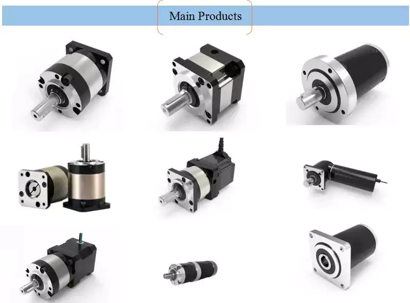
If you’re looking for an affordable way to power a machine, consider purchasing a Planetary Motor. These units are designed to provide a massive range of gear reductions, and are capable of generating much higher torques and torque density than other types of drive systems. This article will explain why you should consider purchasing 1 for your needs. And we’ll also discuss the differences between a planetary and spur gear system, as well as how you can benefit from them.

planetary gears

Planetary gears in a motor are used to reduce the speed of rotation of the armature 8. The reduction ratio is determined by the structure of the planetary gear device. The output shaft 5 rotates through the device with the assistance of the ring gear 4. The ring gear 4 engages with the pinion 3 once the shaft is rotated to the engagement position. The transmission of rotational torque from the ring gear to the armature causes the motor to start.
The axial end surface of a planetary gear device has 2 circular grooves 21. The depressed portion is used to retain lubricant. This lubricant prevents foreign particles from entering the planetary gear space. This feature enables the planetary gear device to be compact and lightweight. The cylindrical portion also minimizes the mass inertia. In this way, the planetary gear device can be a good choice for a motor with limited space.
Because of their compact footprint, planetary gears are great for reducing heat. In addition, this design allows them to be cooled. If you need high speeds and sustained performance, you may want to consider using lubricants. The lubricants present a cooling effect and reduce noise and vibration. If you want to maximize the efficiency of your motor, invest in a planetary gear hub drivetrain.
The planetary gear head has an internal sun gear that drives the multiple outer gears. These gears mesh together with the outer ring that is fixed to the motor housing. In industrial applications, planetary gears are used with an increasing number of teeth. This distribution of power ensures higher efficiency and transmittable torque. There are many advantages of using a planetary gear motor. These advantages include:
Motor

planetary gearboxes

A planetary gearbox is a type of drivetrain in which the input and output shafts are connected with a planetary structure. A planetary gearset can have 3 main components: an input gear, a planetary output gear, and a stationary position. Different gears can be used to change the transmission ratios. The planetary structure arrangement gives the planetary gearset high rigidity and minimizes backlash. This high rigidity is crucial for quick start-stop cycles and rotational direction.
Planetary gears need to be lubricated regularly to prevent wear and tear. In addition, transmissions must be serviced regularly, which can include fluid changes. The gears in a planetary gearbox will wear out with time, and any problems should be repaired immediately. However, if the gears are damaged, or if they are faulty, a planetary gearbox manufacturer will repair it for free.
A planetary gearbox is typically a 2-speed design, but professional manufacturers can provide triple and single-speed sets. Planetary gearboxes are also compatible with hydraulic, electromagnetic, and dynamic braking systems. The first step to designing a planetary gearbox is defining your application and the desired outcome. Famous constructors use a consultative modeling approach, starting each project by studying machine torque and operating conditions.
As the planetary gearbox is a compact design, space is limited. Therefore, bearings need to be selected carefully. The compact needle roller bearings are the most common option, but they cannot tolerate large axial forces. Those that can handle high axial forces, such as worm gears, should opt for tapered roller bearings. So, what are the advantages and disadvantages of a helical gearbox?

planetary gear motors

When we think of planetary gear motors, we 10d to think of large and powerful machines, but in fact, there are many smaller, more inexpensive versions of the same machine. These motors are often made of plastic, and can be as small as 6 millimeters in diameter. Unlike their larger counterparts, they have only 1 gear in the transmission, and are made with a small diameter and small number of teeth.
They are similar to the solar system, with the planets rotating around a sun gear. The planet pinions mesh with the ring gear inside the sun gear. All of these gears are connected by a planetary carrier, which is the output shaft of the gearbox. The ring gear and planetary carrier assembly are attached to each other through a series of joints. When power is applied to any of these members, the entire assembly will rotate.
Compared to other configurations, planetary gearmotors are more complicated. Their construction consists of a sun gear centered in the center and several smaller gears that mesh with the central sun gear. These gears are enclosed in a larger internal tooth gear. This design allows them to handle larger loads than conventional gear motors, as the load is distributed among several gears. This type of motor is typically more expensive than other configurations, but can withstand the higher-load requirements of some machines.
Because they are cylindrical in shape, planetary gear motors are incredibly versatile. They can be used in various applications, including automatic transmissions. They are also used in applications where high-precision and speed are necessary. Furthermore, the planetary gear motor is robust and is characterized by low vibrations. The advantages of using a planetary gear motor are vast and include:
Motor

planetary gears vs spur gears

A planetary motor uses multiple teeth to share the load of rotating parts. This gives planetary gears high stiffness and low backlash – often as low as 1 or 2 arc minutes. These characteristics are important for applications that undergo frequent start-stop cycles or rotational direction changes. This article discusses the benefits of planetary gears and how they differ from spur gears. You can watch the animation below for a clearer understanding of how they operate and how they differ from spur gears.
Planetary gears move in a periodic manner, with a relatively small meshing frequency. As the meshing frequency increases, the amplitude of the frequency also increases. The amplitude of this frequency is small at low clearance values, and increases dramatically at higher clearance levels. The amplitude of the frequency is higher when the clearance reaches 0.2-0.6. The amplitude increases rapidly, whereas wear increases slowly after the initial 0.2-0.6-inch-wide clearance.
In high-speed, high-torque applications, a planetary motor is more effective. It has multiple contact points for greater torque and higher speed. If you are not sure which type to choose, you can consult with an expert and design a custom gear. If you are unsure of what type of motor you need, contact Twirl Motor and ask for help choosing the right 1 for your application.
A planetary gear arrangement offers a number of advantages over traditional fixed-axis gear system designs. The compact size allows for lower loss of effectiveness, and the more planets in the gear system enhances the torque density and capacity. Another benefit of a planetary gear system is that it is much stronger and more durable than its spur-gear counterpart. Combined with its many advantages, a planetary gear arrangement offers a superior solution to your shifting needs.
Motor

planetary gearboxes as a compact alternative to pinion-and-gear reducers

While traditional pinion-and-gear reducer design is bulky and complex, planetary gearboxes are compact and flexible. They are suitable for many applications, especially where space and weight are issues, as well as torque and speed reduction. However, understanding their mechanism and working isn’t as simple as it sounds, so here are some of the key benefits of planetary gearing.
Planetary gearboxes work by using 2 planetary gears that rotate around their own axes. The sun gear is used as the input, while the planetary gears are connected via a casing. The ratio of these gears is -Ns/Np, with 24 teeth in the sun gear and -3/2 on the planet gear.
Unlike traditional pinion-and-gear reducer designs, planetary gearboxes are much smaller and less expensive. A planetary gearbox is about 50% smaller and weighs less than a pinion-and-gear reducer. The smaller gear floats on top of 3 large gears, minimizing the effects of vibration and ensuring consistent transmission over time.
Planetary gearboxes are a good alternative to pinion-and-gear drive systems because they are smaller, less complex and offer a higher reduction ratio. Their meshing arrangement is similar to the Milky Way, with the sun gear in the middle and 2 or more outer gears. They are connected by a carrier that sets their spacing and incorporates an output shaft.
Compared to pinion-and-gear reduces, planetary gearboxes offer higher speed reduction and torque capacity. As a result, planetary gearboxes are small and compact and are often preferred for space-constrained applications. But what about the high torque transfer? If you’re looking for a compact alt